My first voltage regulator circuit
I realize that this is a pretty simple circuit, however for me it was my first! As a part of building a serial Roomba to PC tether interface I’m trying not just follow a schematics and instructions but to also understand every part I’m putting together.
According to Wiki:
A voltage regulator is an electrical regulator designed to automatically maintain a constant voltage level
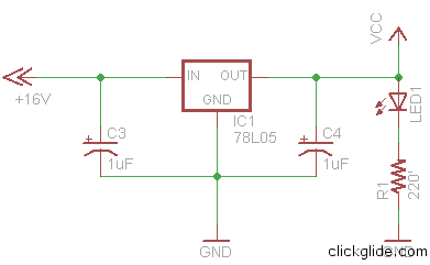
In other words it takes voltage of various values (i.e. from 7-25 VDC) converts it to specific voltage, usually 5 VDC, no matter what the input was. Here’s a diagram of the circuit that I built:
At the heart of the circuit is a 78L05 voltage regulator chip which basically does all the work (you can even say that other components are optional…
78L05 is low power (light) version of standard 7805 Voltage regulator. It’s bigger brother 7805 can handle current of up to 1 Amp, while 78L05 is suited for much lower currents (100 mA). There’s a noticeable different between two in size. 7805 is about 3 times larger than 78L05 and has heat-sink, so you can see advantage of using 78L05 for miniature circuits.
You’ll notice that there are 2 polarized capacitors (C3 and C4) used in the circuit. Both have value of 1uF. C3 stabilizes incoming current if it fluctuates (and it usually does with anything that involves motors) making voltage regulator’s job easier. C4 performs similar role but it stabilizes outgoing voltage which is critical if it will be used with integrated circuits which require a very stable 5 Volts. In addition there’s a LED and a 220 ohm resistor added. LED shows that circuit is working, and resistor is needed so LED doesn’t blow out (by itself LED will drain as much current as possible and die, so resistor will limit it’s “hunger for power”).
So let’s see step by step how it all works. On the left side we have an incoming voltage of +16 VDC (fed by power supply) that is being filtered by capacitor C3. It “enters” IN pin of the 78L05. Middle pin of the voltage regular is connected to the ground. Voltage regulator does it’s internal IC magic and converts +16VDC to a +5VDC which “comes out” of OUT pin and gets filtered by C4. It then lights up LED, and also goes to the rest of the whatever devices you will have later connected to the circuit. You might want to measure current by connecting volt meter to the OUT pin of the voltage reg. and ground. Try changing incoming voltage (don’t go over 20 volts), and see that output voltage will stay at steady 5 Volts.
There at least one way of improving the circuit by adding a Diode at the input which will save your components if you accidentally reversed polarity (diodes let current travel in one direction only). I actually did this by mistake (reversing polarity), and was wondering why LED is not lighting, fortunately I didn’t damage any components.
Tags: 7805, 78L05, capacitor, DYI, electronics, hobby, IC, resistor, roomba, schematics, voltage regulator


