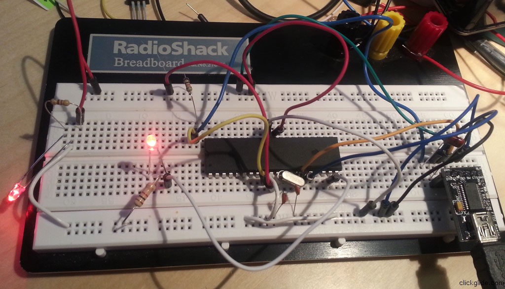
ATMega644p on breadboard
Blank ATMEga644p chip arrived straight from Atmel and I’ve just spent pretty much whole day trying to make it into Arduino clone with a success!
In case you are trying to do the same, here’s the brief description of whole process (from burning Bootloader to loading first sketch).
First of all this method describes burning bootloader with help of official Arduino Board (such as UNO or Mega). You can do it without if you have ISP programmer, but I have no idea how to use it. This was simple enough for me, and I already had 2 official Arduino boards.
First gather parts needed for the project.
- ATMega644p w/o bootloader
- FTDI Usb breakout board (you’ll need it later to load sketches)
- Arduino UNO or Mega (to program bootloader)
- Prototyping board
- 16Mhz oscillating crystal
- 2x22pF ceramic capacitors (code 22)
- 0.1uf ceramic capacitor (code 104)
- 2x1K resistors (or anything from 300 – 1K)
- Bunch of jumper wires
Download Bootloader and Arduino IDE files from http://code.google.com/p/sanguino/downloads/list
As a side note, Sagduino is pretty much what we’ll have in the end, only issue is that Sagduino’s project page, is extremely poor on explanation how to wire and program ATMega644p…
When I started I wanted to power my contraption with DIY voltage regulator based on L7805 IC. I somehow managed to burn it out in the process… Truth is you don’t need it for the breadboard. You will get power from your Arduino board during bootload burning, and then from FTDI module (which get’s 5V form USB). I’m still puzzled why L7805 burned out, it was working fine with 12 V in and gave 5 V out, until I hooked up FTDI board… I’ll investigate later.
Anyway process of wiring everything and burning bootloader with Arduino as ISP programmer described in detail here:
http://reprap.org/wiki/Burning_the_Sanguino_Bootloader_using_Arduino_as_ISP
Unfortunately it hasn’t been updating in very long time, and will take some figuring out. But I can give you few hints.
Do not skip 3 LED lights setup! I almost did, but there’s no way to know if your chip is being programmed correctly without them! So it’s really important. Light on Pin 7 is Programming, 8: Error, and 9:Heartbeat.
If you connect everything correctly and load ArduinoISP sketch, heartbeat light should start pulsing/glowing. That’s a really good sign!
All steps are good up until “Burning the Bootloader”. New Arduino IDE 1.0.1 is little different.
Instead of “Go to Tools/Burn Bootloader and click w/ Arduino as ISP Fig.7” you first need to go to Tools -> Select Programmer ->Arduino as ISP. And then Burn Bootloader.
Wait, it will take few minutes. Once “programming” LED goes out and “Heartbeat” starts pulsing again, you are all set!
Disconnect your Arduino and extra wires. You can keep LEDs. Now connect your FTDI board, and wire it like this:
http://www.flickr.com/photos/maniacbug/6413368937/ (There’s a great guide for wiring ATMega 1284p which is same as wiring ATMega644p).
FTDI will supply 5 volts to your arduino. When hooked via USB to your computer depending on OS you might or might not need FTDI drives. If you do, get them here.
Check your IDE program and make sure you selected “Sanguino w/ ATMega644p” board. That’s it you can now burn sketches to it! If you want to try example “Blink” sketch, just connect LED with 1K resistor to Pin 19 (which is same as Digital Pin 13 on UNO).
Tags: arduino, ATMega644p, bootloader, breadboard, FTDI, programming, sketch


