LED Clock Update: New Name, New Prototype
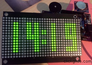
Some big updates on my LED Clock project!
First of all I finally came up with a name: “XRONOS Clock”. “X” is “Chi” and it’s 22nd letter of the Greek Alphabet and reads as “ch”, so Xronos is actually pronounced as Chronos. As you probably know Chronos is God of Time, thus the name. And since new clock enclosure resembles “X” I choose that “Chi” letter.
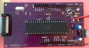
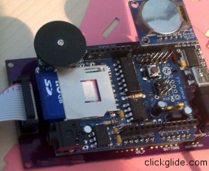
Second, PCBs finally arrived from OSH Park few days ago! I was able to solder all the components to my first prototype and for the most part it works!!!
There were at least 3 issues with the board.
First issue is biggest one with FTDI header, it was interfering with clock for some reason (I suspect TX/RX traces are too close to others). Clock would not run when plugged into USB. Strangely enough on second day those issues seem to be gone, and everything is working great!
Second issue is a design flaw of the power supply. Since I’m using 7805 voltage regulator, it gets VERY hot, especially when using 12V DC power supply. This will be an issue with thermal sensor and overall power efficiency. I did some research and it looks like switching regulator is a lot better solution, but it’s expensive. So I decided to forgo voltage regulator and rely on good 5V power supply instead. I also found super cheap external breakout board with switching regulator that can handle pretty much any voltage up to 40V and convert it to clean 5V.
Finally I realized that I put FTDI headers wrong way, which is no biggie.
I’ve already made new version of PCB and sent it to OSH Park for manufacturing. I was able to shrink it’s size significantly and save me some money 🙂
Improvements I made to the PCB design:
- Removed Voltage Regulator w/ caps and PCB Mounted DC Jack (in favor of panel mounted one) which freed up lost of room and alloed me to move HT1632 header to the left. This allowed me to reduce board size by about 30%! That’s huge, and saved me about $15 on PCB fab costs.
- Got rid of Power terminals to power HT1632 display. I discovered that IDC connector already has pins for power, so I just rerouted it there. Extremely happy about this one.
- Added small diode to parallel to the reset resistor to prevent latching issue (this caused Arduino R2 boards to lock under certain conditions, such as when using DollyShield).
- Added reset connection that goes to Wave Shield. This allows to reach reset button from Wave Shield, because one on my PCB is unreachable.
- Added back power connection from FTDI plugin module so board can be powered by USB. I removed it becuase it blew my voltage regulator when I was testing on breadboard. I’m still not sure how/why it happens, but it works fine now (tested by soldering wires directly to PCB).
- Fattened up some traces such as power in Eagle board design. Generally I’m yet conformrtable of doing all the traces manually, so I used Auto-router and then moved/changed some of the by hand.
I finally designed Acrylic enclosure and sent it to be Laser cut at Pololu. I decided to use Pololu this time, because Ponoko is super slow, they still didn’t start making my DollyShield enclosure which I sent to them 10 day ago! Unfortunately neither company carries 1/4″ thick acrylic that’s transparent grey, so I will have to buy it separately and later send to them. For now I just orders it to be cut in clear acrylic. I still didn’t receive quote from Pololu, I’m afraid it will not be cheap 🙁 Ponoko’s quote came out to be $75!
On my to-do list is figure out and make small amp for the sound. I’ll try to piggybank another Amp chip on top of one that’s already on WaveShield, or create small daughter board. I also made another small revision to my PCB. I will use polorized locking headers for both power and buttons for a more secure connection.


