LM386 based portable audio amplifier under $3
If you project needs small battery powered audio amp nothing beats LM386. It can work with voltage as low as 3V (battery powered) and provided pretty loud yet good quality sound. We are talking around <1 Watt of course, but it’s sufficient for most little gadgets and/or toys.
And best part you build one for under $3. Instructions, part list and video after the break.
Here are parts that you will need (cheapest place to get them is from China, might take 2 weeks or more receive so feel free to get from eBay or local Radioshack, but for more $$$):
- LM386 chip $0.18 each
- Mini perfobard $0.66 each (or $2.49 for two at RadioShack)
- 9x 0.1″ (2.54mm) Male pin headers (or female, depending on your connectors) $0.15 for 40
- 220 Ohm resistor (or substitute with 10K potentiometer to control volume!) $0.03 each
- 10 Ohm Resistor $0.03
- 1uF Electrolytic Capacitor $0.02 each
- 220uF Electrolytic Capacitor (100uF also will work) $0.03 each
- 0.1uF (code 104) ceramic capacitor $0.10 (for 10)
- 47nF (code 473) ceramic capacitor (IMPORTANT to get exact 47nF value!) $0.04 each
- 9Volt battery clip $0.10
- 0.5Watt 8 Ohm speaker $1.28
That’s just $2.62 in parts not including 9Volt battery! Of course if you order from taydaelectronics.com there’s a $5 minimum order so feel free pickup other parts 🙂
You’ll also need soldering iron, solder, some hookup wires and of course 9 Volt batter (or feel free to use other DC power source, as long as it’s 3V-12V).
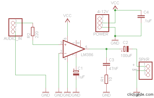
Take a look at schematic (or download Eagle files here)
I suggest your first build it on breadboard and test before soldering to the perfboard. You should also check LM386 datasheet to see it’s pin arrangement, but to make things easier here’s pin numbers:
You see that rounded notch on top of the chip? That’s how you know where Pin 1 is located (to the left of the notch). Most IC pins arranged like that (left side from top to bottom, and then right side from bottom to top)/
In my diagram I’m using 3 pins in each header while only 2 is needed. Reason is so it’s harder to connected plugs using wrong polarity. You don’t have to use any of the headers because you can just solder connectors directly. Especially battery terminal. Connect all grounds together. Pay attention to electrolytic capacitor polarity.
As I mentioned earlier instead of 220 Ohm R2 resistor you can use 10K potentiometer (variable resistor) to control volume. I don’t have any pcb mounted pots so I just put regular resistor. You actually don’t really need one, but I think some MP3 players will detect if you plugged them if you have resistor in the input (I could be wrong).
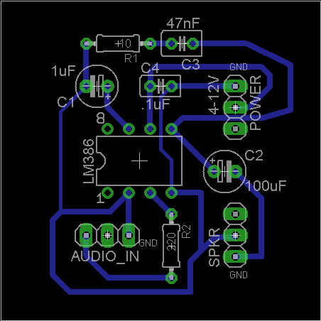
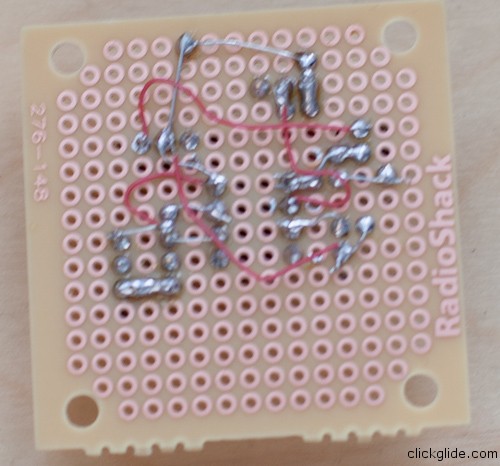
Here’s picture of the board layout I did in Eagle. You can follow it to make your own traces with wires on perfboard.
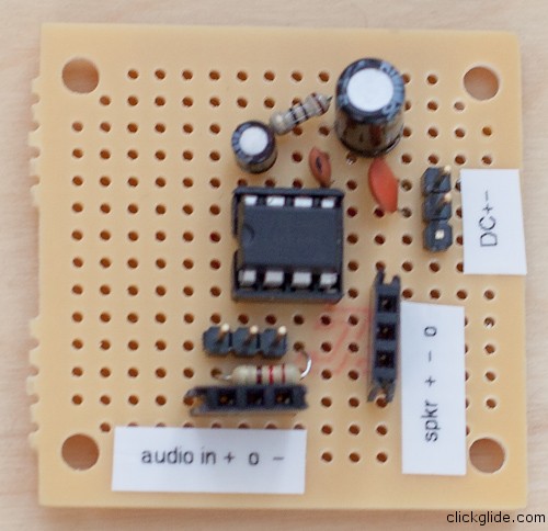
Finally here’s result and video. Download Eagle Project files here
Let me know if you have any questions 🙂
Tags: amp, amplifier, audio, battery, cheap, diy, LM386, portable


