Rapid BootLoader Shield
What is it?
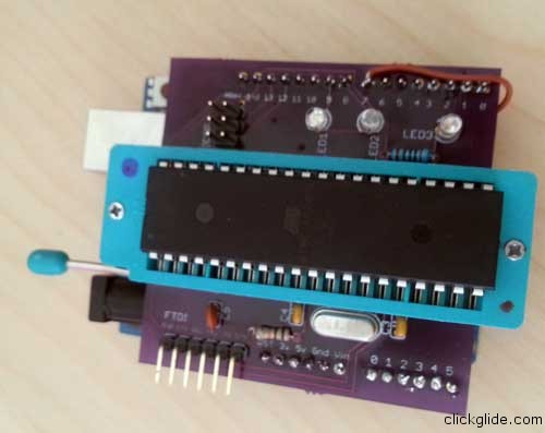
Purpose of the Rapid BootLoader Shield (or RBS) is to quickly program 40 pin ATMega microprocessors (currently supported ATMega644p and ATMega1284p). It’s a no frills open source shield that plugs into Arduino Uno, and using Arduino as ISP allows to quickly burn Sanguino (or other) bootloaders quickly thanks to the ZIF (Zero Insertion Force) socket. It also has FTDI interface so you can program your sketch. No need to remove it from Arduino in the process.
It’s very useful if you need to program many chips in a hurry without much of an effort. I’ll provide all schematics and instructions below so you can build one.
Features
Not many to speak off 🙂 It has 40-pin ZIF socket, FTDI and ISP headers and 3 indicator LEDs (Green,Red and Blue) that will indicate you process of loading firmware/bootloader.
How to use it?
Before you begin you need to have Arduino IDE installed and Sanguino files added to hardware folder under your Arduino project. Note that I only tested it with Arduino 1.0.1
Installing Sanguino support files is easy. Download latest Sanguino zip from link above, create “hardware” folder in your projects folder (if it’s not already there) and extract all files into it (you should now have “sanguino” folder inside).
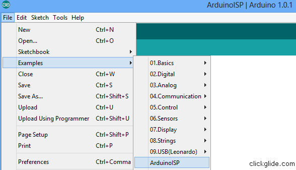
1. Do not connect RBS to Arduino yet. Connect Arduino to your computer, open Arduino IDE and load “Arduino ISP” sketch from Examples (File -> Examples -> Arduino ISP)
2. Make sure you have Arduino Uno selected from Tools->Board.

3. Also select appropriate COM port and Upload sketch into Arduino
4. Now disconnect Arduino from computer, and insert Rapit Bootloader shield.
5.Open lever of the ZIF socket and place your ATMega chip (notch or 1st pint should point towards lever). Close lever.
6. Reconnect Arduino to computer. Green heartbeat LED1 on RBS should start pulsing.
6. Go to Tools->Board and select “Sanguino w/ ATMega644p” or ATMega1284p. If you don’t see it the list it means you didn’t install files required for Sanguino.
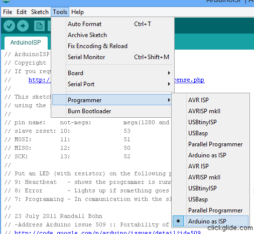
7. No click on Tools->Programmer and select Arduino as ISP
8. Go to Tools->Burn Bootloader.
At this point LED1 (heartbeat) and LED3(programming) will begin blinking. Burning bootloader might take few minutes so be patient. Once it’s done you’ll see success message and heartbeat led will begin pulsing again.
Feel free to connect your FTDI adapter and load test sketch into newly programmed chip. Just lift lever to remove chip (but unplug power first, just to be on the safe side!).
Here’s video demonstration of how it’s programmed:
How do I make one?
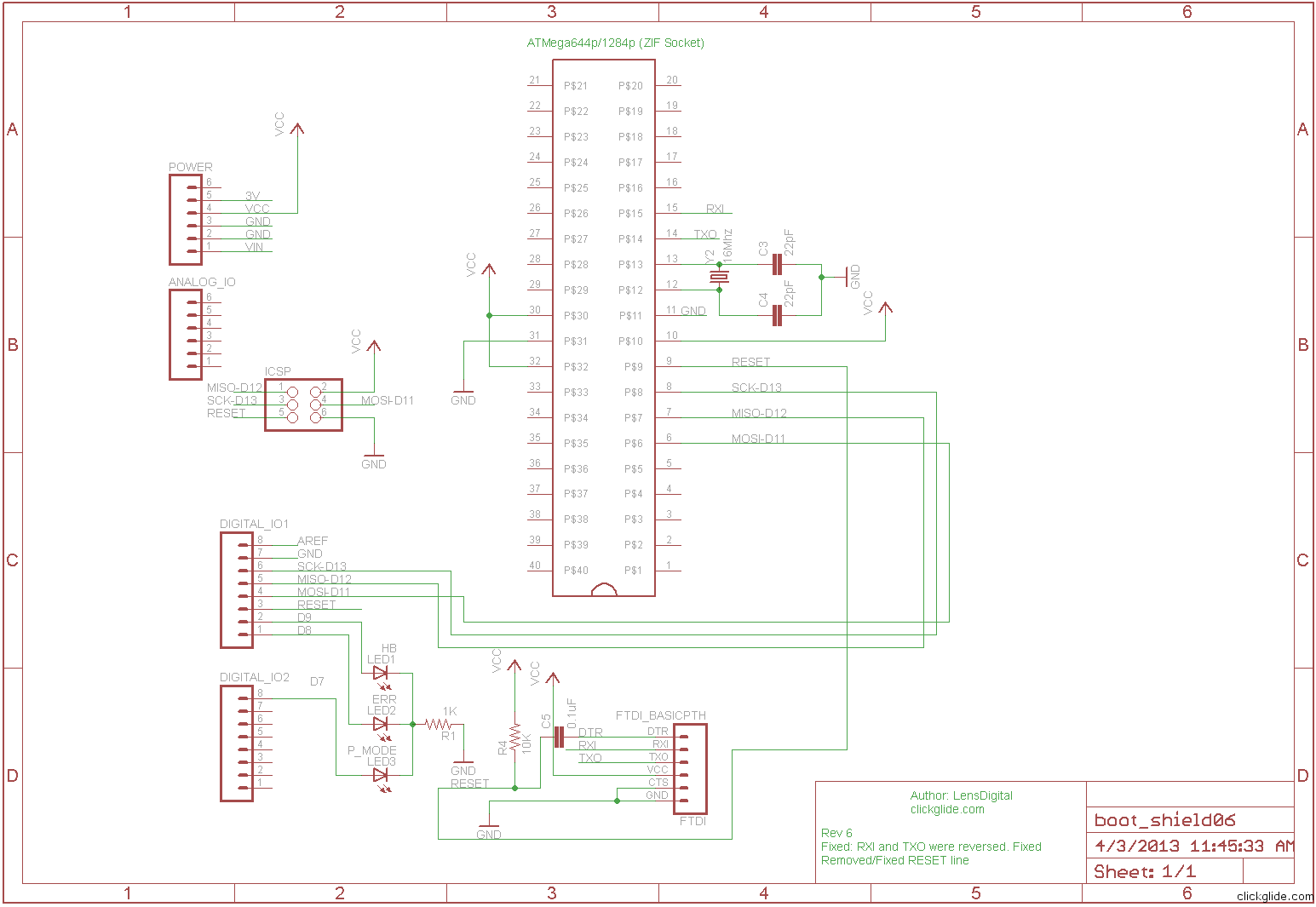
RBS is completely open source. Feel free to make it, just give me some credit please 🙂 I only made single prototype and it had many errors so I had to cut traces and solder jump wires all over. At this point I think I corrected all mistakes but doublecheck schematics before you make our own PCB.
Here’s schematic (click on enlarge):
And this is board:
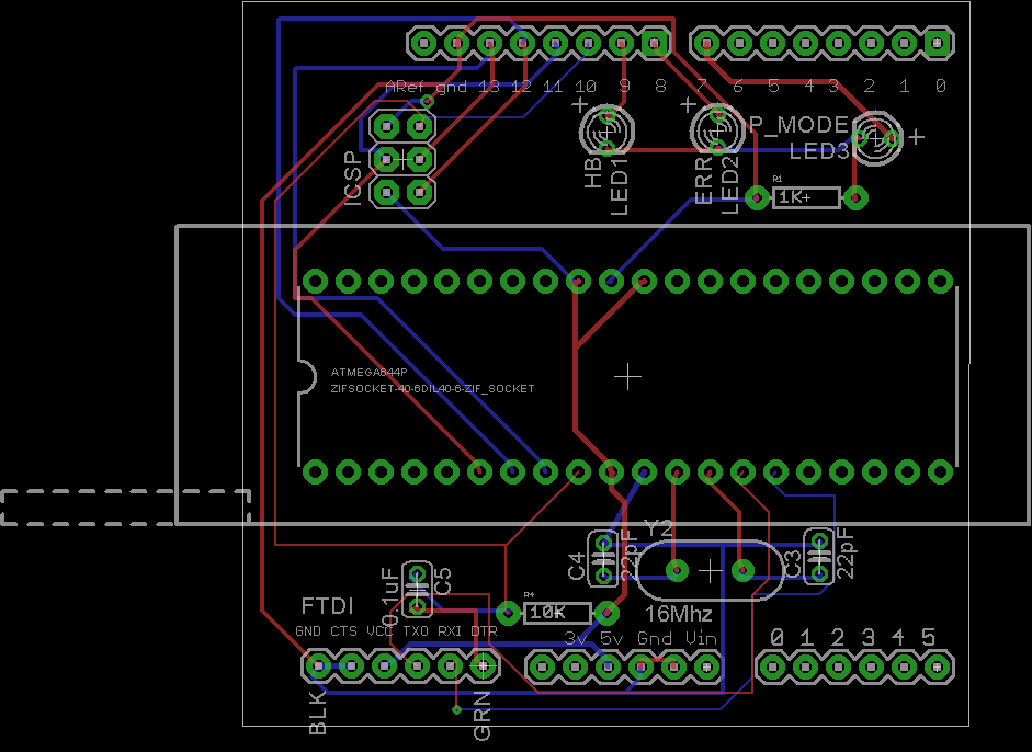
Click here to download Eagle files.
Let me know if you interested in buying one. If I get enough requests I’ll make a small batch.
Tags: arduino, ATMega644p, bootloader, custom, diy, how to, opne source, oss, shiled, tutorial